
Prius Cargo Dome LED Conversion (V1)
Purchase
The factory cargo lamp never turns off if the hatch is left open, and it draws 5W while producing a yellowish, inadequate amount of light. The solution was to make a drop-in LED conversion with a constant-current driver. Running at 350mA, this module consumes just over 1W and produces far more light than the factory bulb. Drops right in, in place of the bulb. Modification is 100% reversible.
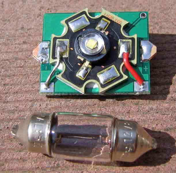
Here is the LED module next to the factory bulb that it replaces.
This shows the LED module installed and on (in full sun with
hatch open). This picture also shows where to pry to pop the module out of
the hole. You have to pry pretty hard the first time, but there isn't much
to break. Don't try prying from the other side though!

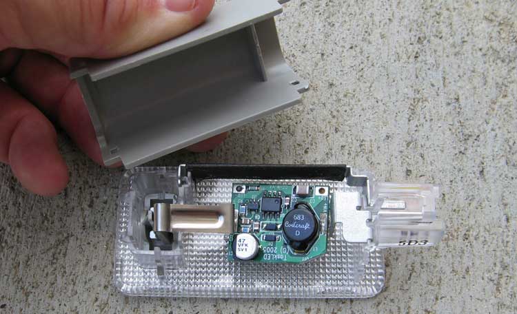
The gray plastic cover on the back of the module just pops off
easily (held on where the four square holes are). Removal of the stock bulb
is straight-forward - just bend the springy tab out of the way. (You will
not see that circuit board in there, obviously. Picture taken AFTER conversion).

Installation.
The new circuit board should end up as shown below - with the
positive side toward the power connector. The board obviously needs to be
oriented so the LED faces the diffuser - duh). Just snap the pins into the
same contact holes as the factory bulb used. The switch is the craziest thing
I've seen in a long time - the entire bulb (or circuit in this case) moves
as the switch is operated. Sometimes the circuit can get bound up with all
the flopping around, but since I rarely use the switch any longer, it is not
much of a concern. I will show were to use a drop of adhesive to fix that
issue if it is a problem in your situation.
1. First step is to add some insulating tape (shown here - black tape) to
the bar that reaches past the circuit to provide the negative contact. Cover
the entire bar to avoid the possibility of shorting the components on the
circuit board. A precaution since the circuit could touch that bar. Any tape
will do that will stay in place. Also shown here is the correct orientation
for the gray cover which will only snap back on one way around.
2. To begin installation, be sure the switch is in the off (down)
position (this is only to make installation easier - I assume the wire connector
is already off as well), and place the negative pin in the springy end (away
from the wire connector).
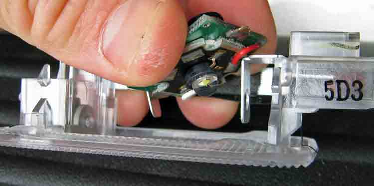
3. Push the circuit board against that spring until you can
poke the positive pin into the hole on the more rigid (wire connector) side
- like this.

All Done. Notice that the board is crooked (like the factory bulb was) and
that the red wire from the LED is toward the wire connector side of the fixture.
4. Snap the wire connector back on, and flip the switch. Got
light? Good!
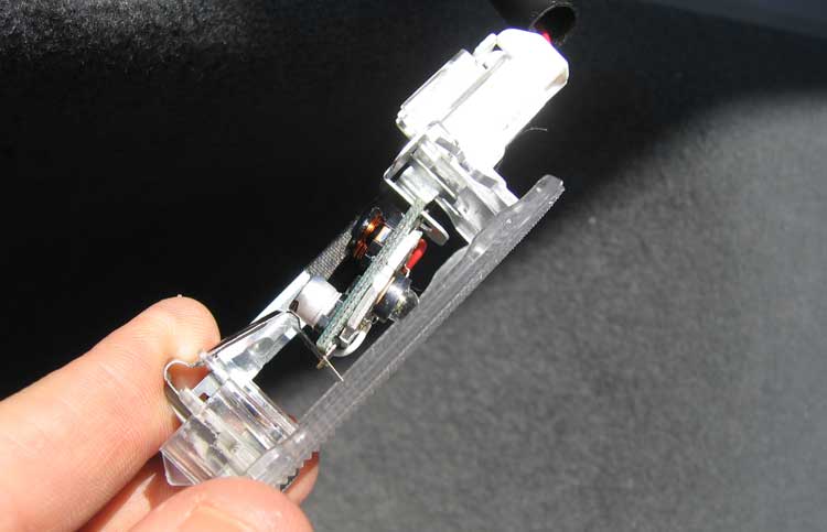
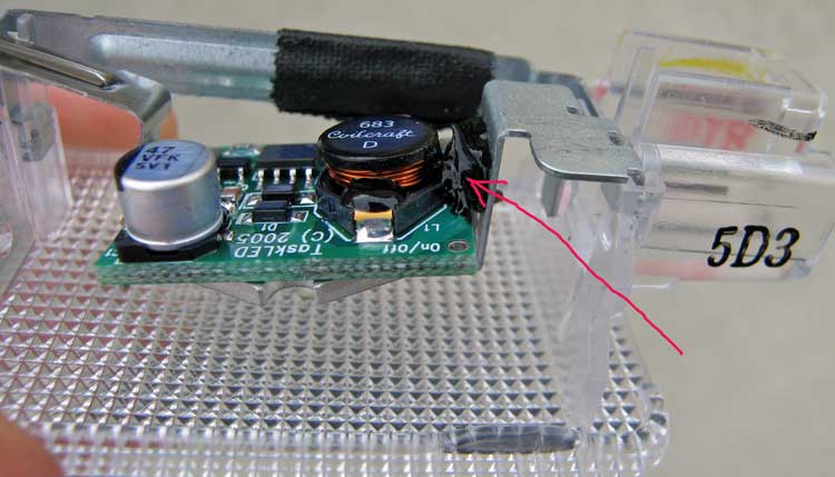
5. Cycle the switch a few times after installation to see what
happens in there, and why I think the switch is so crazy. If the board rotates
after a bunch of switch-flips, you may want to add a drop of silicone adhesive
to the + end. That'll keep it in place, and aimed correctly all the time -
it will flex with the movement of the switch, and it'll be easily removable
if you need to take it back out. Blob of black silicone shown by the red arrow
here. (another shot of (not enough) tape on the bar in the background as well.).
6. You can now snap the gray cover back on, making sure it does not interfere with the circuit board. If there is interference, the cover can safely be left off. Snap the assembly back into place, and you're good to go.
Click for |