Prius Horn Signal
This mod, by George Myers (patcoghm@sbcgobal.net), makes the horns beep when when the SmarKey buzzer sounds.
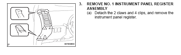
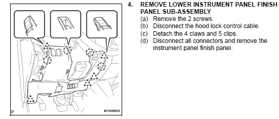
First step is to remove the register, lower Instrument panel, and glove box. Follow steps 3, 4 and 10-14 below.
Note:
Step 4 Not all steps are needed when removing the lower panel.
We are going to let it hang and not totally remove it.
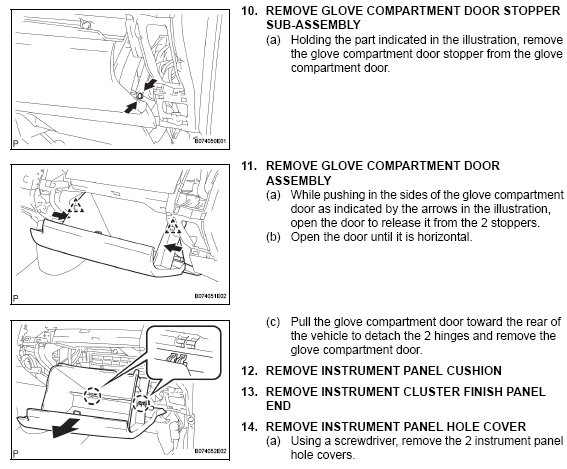
Step 10 They call it the door stopper, but I call it the shock absorber.
Step 11 These are the stoppers that keeps the glove box in.
Step 12 - 14 not needed.
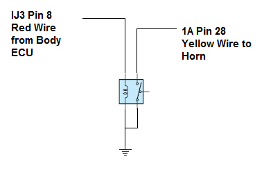
The Circuits Used
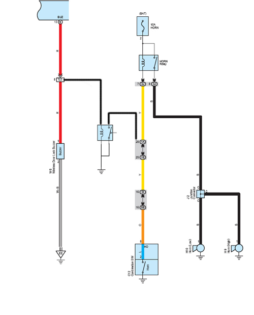
This is the two circuits used to allow the Smart key buzzer
to activate the horns. The Micro Relay is in the middle
and attached to IJ3 Pin-8 and 1A Pin-28.
The Mod
The circuit added is simple, cost less the $ 10.00, and is easy to make.
Junction Plug IJ3 Pin-8
After the glove box is opened, disconnect the little shock on the right side
by pulling it off the pin its attached to. Press the sides in near the center
catch
stoppers that holds the glove box in. When you flex the sides inward the center
catch stoppers will clear the side edges and will open to the point of hanging.
The glove box is attached at the bottom at two points and will pop off for
removal.
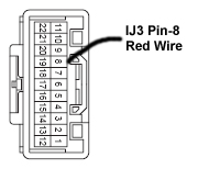
The view below is the area we are looking for. The plug hole with a stick
pin is the IJ3 Pin-8 hole and is a red wire. The pin I used is reshaped to
straighten the T top to a straight line. Then I used a piece of heat shrink
and slipped it over the pin area where the wire is soldered. Next put some
heat to the shrink wrap over a flame (Gas Stove) and the shrink wraps tightly
around the soldered area. You can use electrical tape, but make sure we cover
most of the pins exposed area. Attach a wire long enough to reach thru an
opening
of the dash to the Drivers side junction box.
NOTE - This Pin can be easily removed to disable the horn sound for the normal
beeper.
Junction Plug 1A Pin-28
The drivers side lower dash panel and vent register must be removed.
1. Pull the left air vent register backward from the top (Toward the rear
of the car).
It just pops out. As you will see the whole dash is just popped together.
Pull the
bottom of the vent so the vent comes straight back. (They have a Tool)
2. Remove the screw near the bottom of the vent area holding the lower dash
cover
that runs under the steering wheel.
3. Go along the top edge of the lower panel and find the second screw about
4-5
inches to the right and remove.
4. Pull the lower panel and pop it out. The panel above it might try to pop
out also. Separate these panels as the top half is not required to be removed.
Wires are attached to the panel, so let it just hang. We need just
enough access area to attach the wires and the IC Board and Relay.
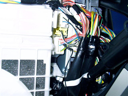
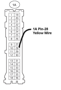
5. Look for the Drivers side junction box.(Picture Below) Its behind a flat
metal plate held
by three nuts. Remove the nuts and the plate. You now have a good view of
the junction
box and the plugs as shown below.
6. Plug 1A Pine 28 is shown and is a yellow wire.
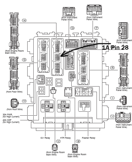
Piggy back a stick pin into the same 1A Pin-28 hole. Tie this wire so it
will
not vibrate out or be pulled out by accident. A plastic tie or black electrical
tape can be used to hold it in place.
Ground Connection
Next solder a wire to a alligator clip and attach the clip to the same metal
frame
the plate was removed from. You can attach it with a connection lug or other
method.
We now have the three wires needed to attach the circuit board.
Building the IC Board with Relay
Cost 6.78 + tax + wire + a little soldering......................
Part # 276-0159, Radio Shack IC PC Board 276-159......2.29
Part # 275-0240, SPDT Micro mini 5V DC Relay............4.49
--- I had these items in my junk box.---
Part # 278-1224 Stranded, 22-gauge wire......................5.59
Alligator clip but not required.
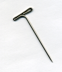
Size no. 24, 1 1/1 in. T-Pins, used in sewing.
No wires are cut. The T-Pins are used for the 2 plugs I piggy
backed my wires into, via a stick pin connection.
One alligator clip to connect the ground to the metal frame.
This is the T-Pins used to piggy back 2 wires into the junction
plug holes. No wires are cut and it fits in the hole snug with the
existing wired pin. NOT ACTUAL SIZE
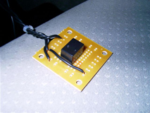
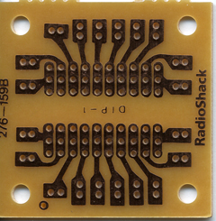
The IC Board side that components are attached to.
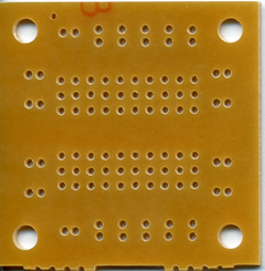
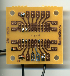
The IC Board side that we solder the wire leads to.
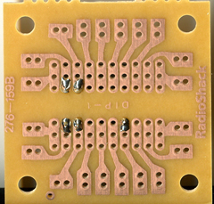
Insert the relay on the component side with the wire
leads sticking thru the IC Board to the copper etched side.
On the copper etched side we solder the 5 wire leads from
the Micro Mini Relay. Notice the position used and I
suggest you duplicate this position.
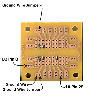
Then insert the 4 wires as shown below from the component
side (other side) thru the holes to the soldering side.
1. The ground jumper wire is a short wire that goes on the
component side (other side) between the 2 points shown below.
2. The 1A Pin 28 point connects a wire that has a T-pin on
the other end. This T-pin is piggy backed into the 1A Pin 28
junction plug hole, located on the drivers side junction box.
3. The IJ3 Pin 8 point connects a wire that has a T-pin on
the other end. This T-pin is piggy backed into the IJ3 Pin 8
junction plug hole, located behind the glove box.
4. The ground point wire has a alligator clip attached on the
other end. The alligator clip is attached to the same metal frame
that holds the metal plate removed to access our work area.
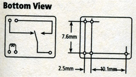
A view of the relay from the Radio Shack Package....
Compare the layout of the IC Board above and the view
of the relay. They are in the same orientation in both views.
When the Body ECU wants the beeper to activate, it
sends a positive voltage and the beeper sounds. This positive
voltage is attached to the IJ3 Pin 8 point above, which energizes
the coil. The coil sets up a magnetic force that pulls the switch
contacts closed. The closed switch contacts sends the ground
signal from the ground wire point, thru the closed contacts, and
out the 1A Pin 28 point to the horn circuit. This ground signal
sounds the horn.
Solder the wires on the copper etched side.
You now have three wires to connect as indicated above.
You're done. I wrapped the IC Board with electrical tape to
insulate the copper etched side from shorting out. I then
put the board above the lower steering wheel cover. It lays
there without any other car parts near it. A square of double
sided tape will hold it in place, or a plastic tie will work.
Click for |