Fog Lights
Modification that allows the fog lights to be on separate from the headlights. The whole point of fog lights are to shine a light down low to the road so that backscatter reflected off the fog doesn't blind the driver. If the headlights need to be on as well... most of the purpose of the fog lights is for naught. This mod will allow the fog lights to be on as long as the parking lights are also on (the reason for this is so that you are not inadvertently invisible from the rear when driving with just the fog lights on). Please note that the factory fog lights are all but useless in lighting the road... that's a whole 'nuther project. This mod just gets them lit correctly. (Original instructions and many photos borrowed from the bobc post on Prius Chat, which in turn was taking from Evan Fusco's knowledge base article.. and was then modified here by Darell.)
Here is another great run through as well: LINK
Required Tools:
#2 Phillips head screw driver
Work light that can be used hands free
Slip-joint pliers
Needle nose pliers--Optional but helpful.
Materials:
1. Rectifier Diode, Forward Current: 1Amp (Radio
Shack 1N4004 #276-1103). 2 per package, $0.89)
2. Telephone Wire Tap Connectors (Radio
Shack 64-3081)
3. Optional: Soldering iron, solder, a few inches of 22-18 gage wire, some
removable wire-splices, shrink tube
Time and Difficulty:
Start to finish may take one hour. This modification
takes very little actual work but is time consuming just to confirm that you
are working with the correct wires and working in tight quarters under the
dash. The modification is quite simply tapping into two wires. If these wires
were out in the open, the modification would take less than 10 minutes. The
modification, while as straightforward as the Coastal Electronic Technologies’
EV mode or Power Outlet modifications, just takes longer due since there’s
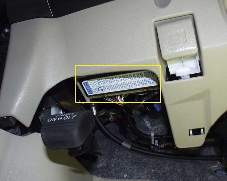
only enough room for one hand when two would make this real easy. This photo
was taken from the floor and is of the lower portion of the dash and the fuse
panel on the driver’s side of the car. You need to access two wires
on the backside of this panel.

Because of this, I rate the modification Easy to Moderate in difficulty.
Additionally, if you have back issues, you probably will not want to do this modification as it requires lying on your back on the driver’s floor well with you head under the dash.
Process in Brief:
-- Remove the lower trim panel of the dash located
under the steering wheel.
-- Locate and release the harness from the driver’s side junction box.
-- Tap into two wires on this harness with the phone taps
-- Insert a diode into these tap-ins.
-- Replace the harness into the junction box and replace the dash trim.
-- Test
Detailed Process:
Before proceeding, be sure all power is OFF to your Prius.
1. Remove the lower trim panel of the dash. This
is the panel that houses the dash lights dimmer switch, the key fob slot and
the Smart Key System (SKS) on/off switch (if so equipped). It’s partially
outlined in blue on this photo:
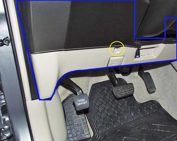
1a. Remove the Phillip’s head screw circled in yellow in the previous photograph.
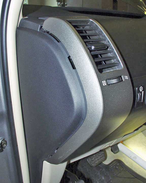
1b. Remove the register assembly on the left-hand
side of the dash (This is the curved silver piece that has the air vent in
it). Some folks have used plastic spatulas to pry the top of the vent from
the dash. Do a search for XM radio installations on this site to find photos
of these. I’ve been able to just pull on the vent and have it release.
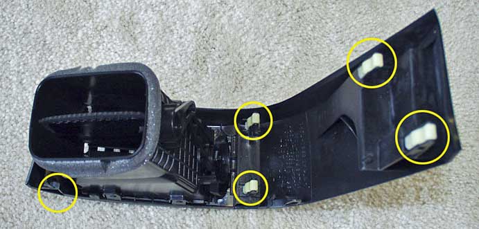
It’s held in place, for the most part, by four plastic clips. To remove
the register, pull it towards you. Start by pulling the top of the register
free, then work your way down. These photos show the register after the pins
clips have released and the backside of the register so that you can see how
the clips and guides (circled in yellow) are arranged.
1c. Remove the second Phillip’s head screw
that was covered by the register.
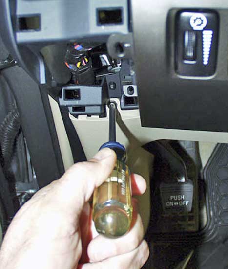
1d. Pull the lower trim panel off. It is held in place by clips similar to those on the register. Start at one of the lower corners and pull straight away from the dash. The upper trim panel of the dash (The one that houses the ‘ON’ button may also release. This is not a problem. Just hold the upper panel down while you continue to pull the lower panel free. Once the lower panel is free, go ahead and snap the upper panel back in place if it has popped free.
Sometimes, the yellow plastic clips fall off of the trim panel. No worries, you didn’t break anything. Once you have the trim panel off, you can snap them back into place.
1e. Remove the four wires that are plugged into the backside of the lower trim piece. One harness is connected to the dimmer switch, two harnesses are connected to the key fob slot and one harness connected to the SKS on/off button.
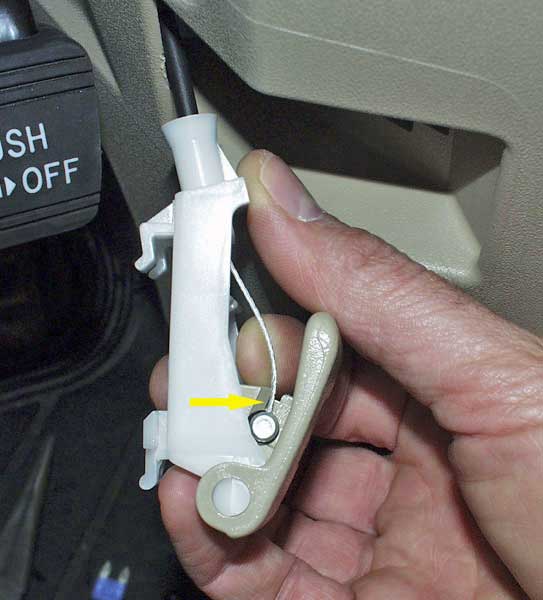
1f. Unclip the hood (bonnet) release latch from
the trim panel. The release handle will not slide out of the trim panel (Actually,
it will, if you force it). Easily pop the handle off by guiding the cable
into the slot (Identified by the yellow arrow in the photograph) to let the
cylinder on the end of the cable to pop free. The latch can now be removed
from the cable. Set aside the lower trim panel.
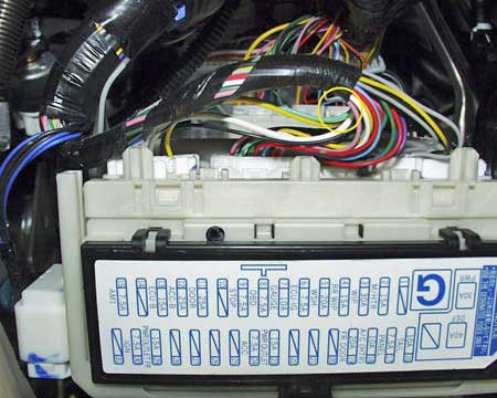
2. Determine which two wires need to be tapped.
Prior to crawling under the dash, I’d suggest that you temporarily tie the hood release cable and the SKS wire up out of the way. These hang down and you wouldn’t want to get poked in the eye by them. The SKS wire is just the perfect length in that it’s always bumping into your nose or hovering right in front of your eyes like a mosquito if allowed to dangle!
Lying on your back, look up on the backside of
the junction box. Yep, I know, there’s a ton of wires back there. You
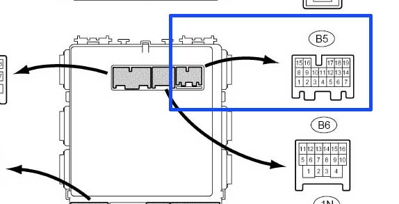
are looking for two in particular. These photos and the diagram should help
you with orientation. The first one is of the fuse box cover and the backside
of the junction box. It is a view similar to what you see when you lie with
your head under the dash. The harness that you need to access is the one located
at the top of the box, in the upper right-hand corner (viewing the box from
the backside) In the first photo, it is partially obscured but look for the
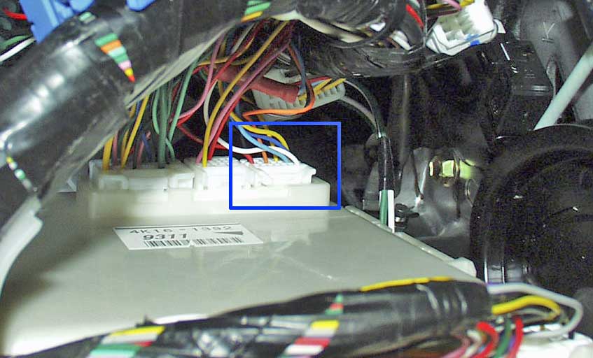
yellow circle identifying it. The second photo is the same view but looking
past the harnesses plugged in at the bottom of the junction box. The harness
is outlined in blue in this photo. The third image below is the diagram of
the back of the junction box. Your quest is the harness labeled B5 on the
diagram. The last photo in this set shows the harness after the clip has been
released from the junction box.
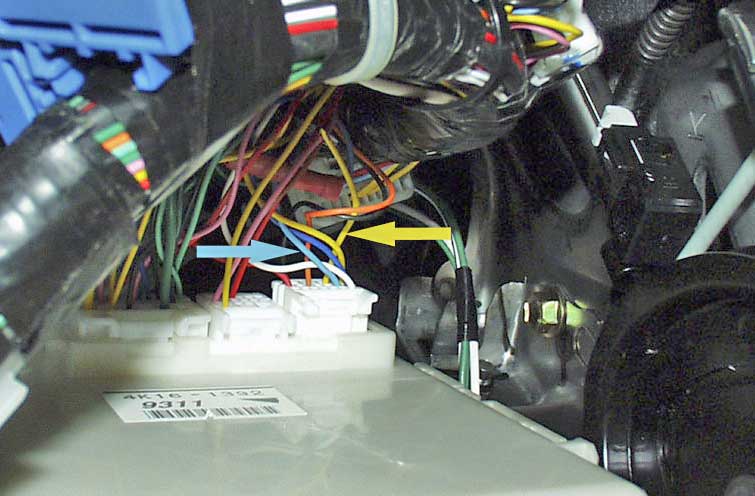
Once the harness has been unplugged, identify the Sky Blue wire attached to
pin #13 in the harness. Identify the Yellow wire attached to pin #17 in the
harness. There are two yellow wires close to one another in this harness.
Confirm that you have the one in the #17 slot using the following diagram.
These wires are also identified by arrows in the above photograph.
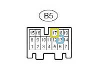
Separate the two wires from the rest of those
in the harness to give yourself some working room. You will be placing the
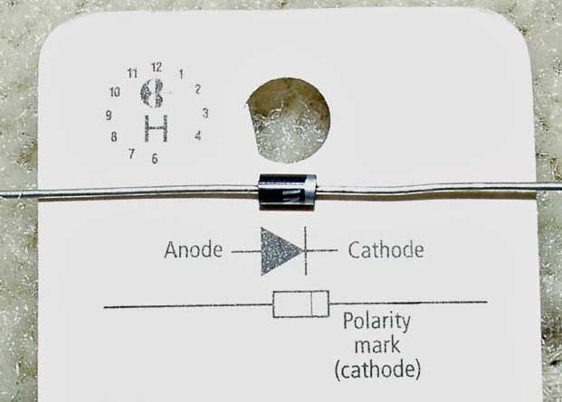
two phone taps on these two wires, with the diode between them. The cathode
side of the diode goes to the Sky Blue wire plugged into pin #13 on the harness.
Cathode to #13 sky blue.
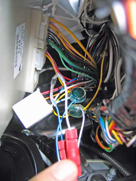
3. To make this easier, I used the phone connectors
to tap in two lengths of wire, and then attached these pigtails to the diode
(shown below in clear shrink-tube). I used some blue wire to extend that one,
but only had white wire to use to extend the yellow one. I soldered similar
wire onto the diode leads, and then used a removable connector to attach those
wires onto the ends of the taps - just in case I screwed up! Doing this made
everything easier to work with. I did all soldering at my bench, and then
under dash all I had to do was connect the diode wires to the wires that came
out of the taps - and this was done with the removable connectors (red) below.
4. Plug the harness back into the junction box, making sure that the metal diode leads don’t touch anything else that’s metallic and test. You won’t need to hook the wires back up to the components on the lower dash panel in order to do this. Turn only the parking/running lights on, not the headlamps. Now, turn the fog lights on. The fog lights should now light up. If not, turn the lights off and re-check your connections.
5. You’re there! Replace the lower dash trim panel. Start by threading the hood release cable back through the dash and connecting it to the release handle. Re-attach the four harnesses to the components on the back of the dash trim. Don’t forget to plug the SKS harness back in, in the event you tied it up out of the way somewhere. The dash panel will snap back into place. Put the two Phillip’s screws back in and snap the air register back in. Take time to line the snaps in the panel and register back up prior to pushing on them. They pop back into place much easier than they came off. If you’re pushing hard and they are not popping into place, something’s wrong.
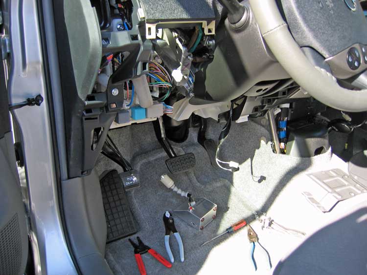
Here's what it looked like about half way through:
 |
Click for |