TAL Paddle Replacement
When a paddle gets damaged, sometimes it can be patched back up and returned to duty. But sometimes, as in this case, there is no hope. Once the wires have been ripped out, and the little circuit boards have been crushed, there's no other solution but to replace the paddle/cable assembly. Provided here are a few pictures and a rough outline (not a step-by-step set of instructions) of how to go about it. If you are confident enough with using tools, and in taking the cover off, you are likely the type of person who can figure all this out for himself. I'll give some hints to make it easier - but know that it has been a while since I've been inside of one of these charges. I can't recall all the details or the order that things happen!
2017 update: Darren Overby created a video that shows the task in real-time, and includes a few new tricks that may make the process go a bit smoother. Darren's Video.
2016 update: The Saxtons show their method.
First off, I wanted to record the two screw sizes that hold the lower bracket/air deflector on: two each of: M6-1.0 and M8-1.25. Great of them to use two different sizes, yeah? OK... onward.
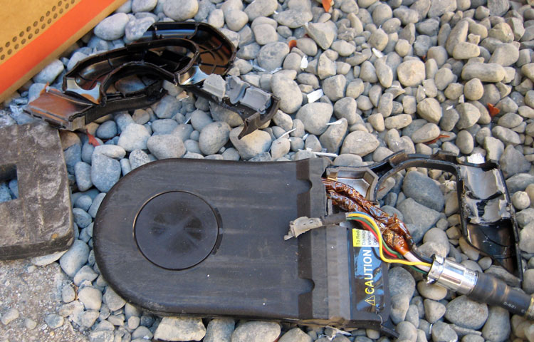
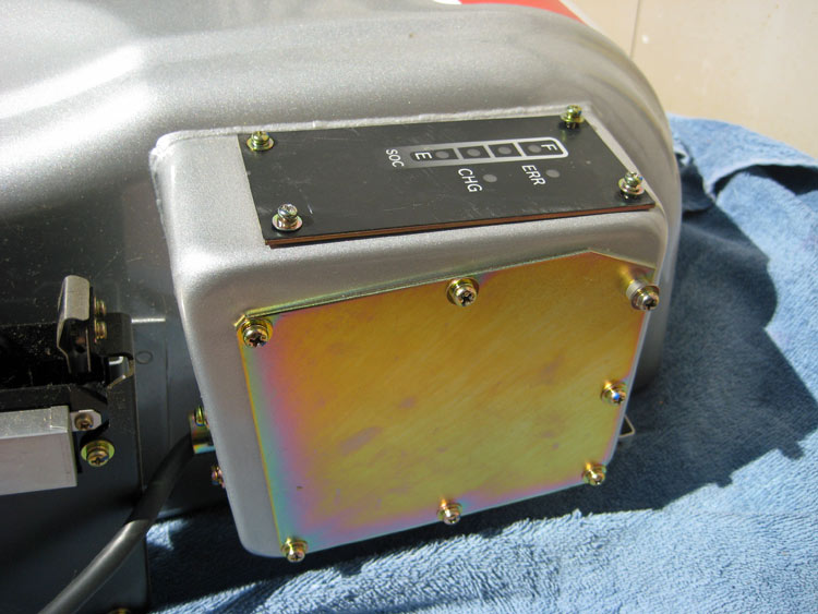
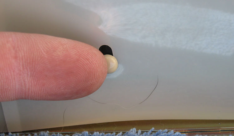
TAL paddle broken beyond repair. Nothing else but replacement will work here.
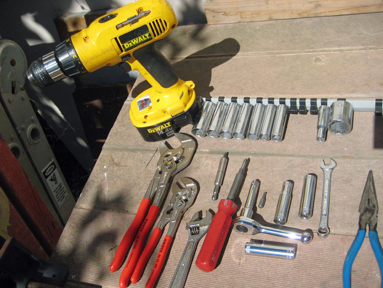
Here are all the tools I used.
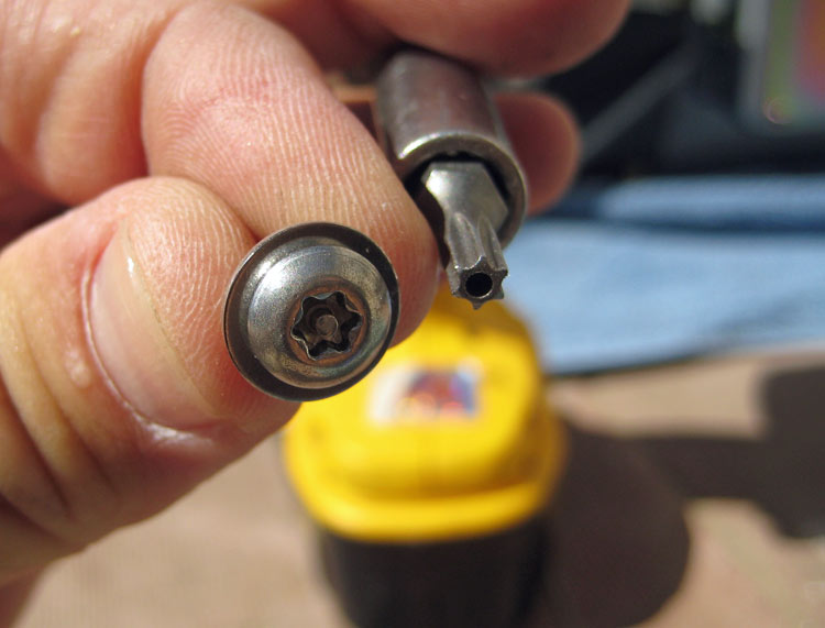
Only specific tool for this job is the security Torx bit shown here. Six-point, size T20H
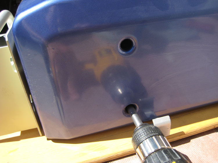
Use the bit in an extension holder for the bolts that hold on the plastic blue cover.
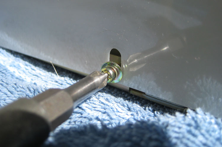
With the plastic blue cover off, you can take off the lovely gold plate held on with WAY too many screws. I'm not sure what they think they're protecting here. Two screws would have been overkill... Note that one of the screws has a standoff. I don't know why, but there it is, and I made sure to replace it in the same position.
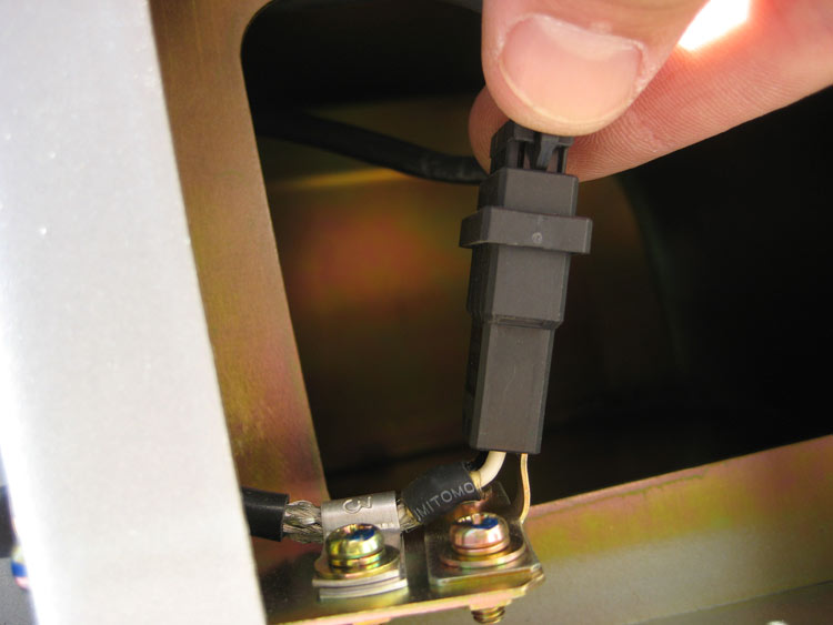
The whole reason you took that panel off was to disconnect two harnesses that are hidden in here. This one, and a small one deeper inside that attaches to the LED display. Remember that both of these will need to be fed back up into this cavity and reconnected at the end..
Not sure why I took this picture. Use a screw driver for the screws you'll find holding part of the cover on!
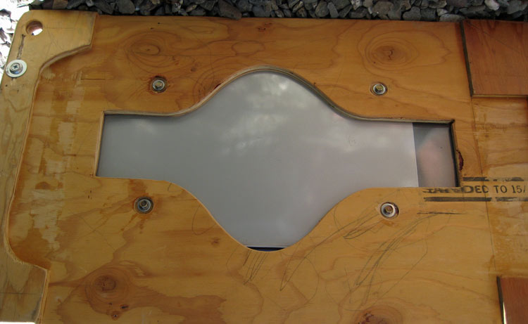
And finally remove the four screws that go through the back. This image is of my plywood-mounted portable TAL. The screws normally just go in through the back skin. You can tell that I used to build violins before I became a professional charger repair guy, right?
With all the screws out, the cover should lift (wiggle and pull) off 0f the base. Now you'll be confronted with a big white plastic shroud protecting the high voltage connectors. The shrouds are held on with little screws or these plastic nubbins. Unscrew or pop them off the nubbins and pull the plastic out of your way. Your charger may or may not come with the dog hair shown in this image.
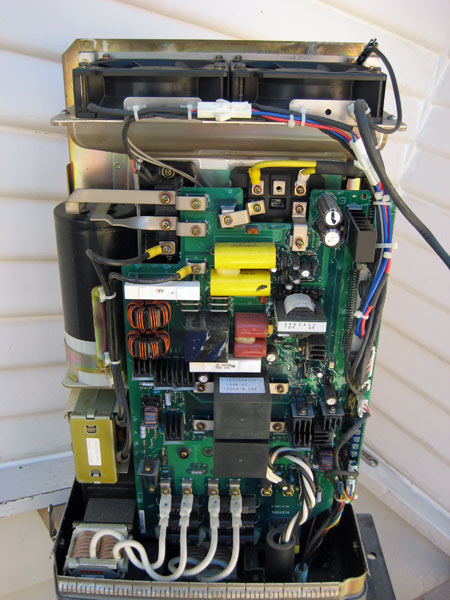
Finally, you've got the whole enchilada in front of you:
This image shows one of the plastic shield screws on the left that'll need to be removed. And the next step is to unscrew this sister board on the right side (as you face it) of the charger. This needs to be moved to access the RF lead (brown wire) from the paddle/cable assembly.
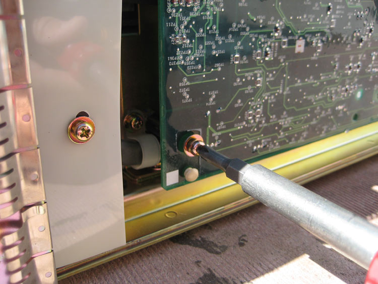
With the screws removed, the sister board can be pulled (pulled and wiggled) straight out from the side of the charger. This giant connector needs to be disengaged.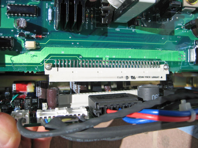
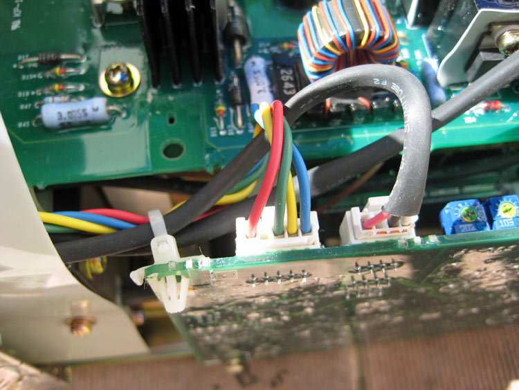
Here is the connector (left-most with red, green,yellow, blue) that is part of the paddle/cable assembly - it is plugged into the top edge of that sister board you just pulled away. The old connector will need to be removed, and the new one snapped back in. This connection can be made with the sister board in place or pulled away.
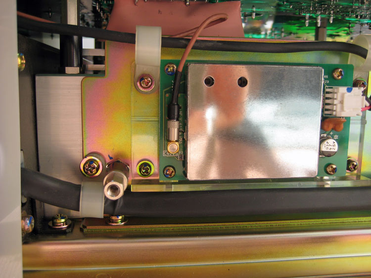
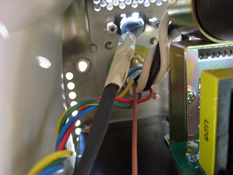
And finally, the reason you had to remove the sister board, The brown wire is the RF connector. This is a typical friction-fit antenna connector. It can just be wiggled/twisted off and on. Needle-nose pliers may come in handy here. Use them on the knurled connector - NOT the wire.
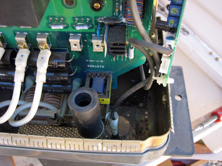
In this shot, the old cable is totally removed. the connector from the sister board is gone, the RF wire is gone, the power wires are gone. Nothing but a hole through the bottom (right side) of the charger. When removing all the wires, make a note of their routing and where they end up!
The new paddle/cable flange. Pass all the wires back up through the hole, and remember to put that thin fixing nut back on before you start to connect the wires to the charger. Route all the wires back into the charger the same way they came out. There are really just three items in this bundle. The colored wires that go to the one connector on the sister board. The two power wires (big white and big black) and the brown RF wire.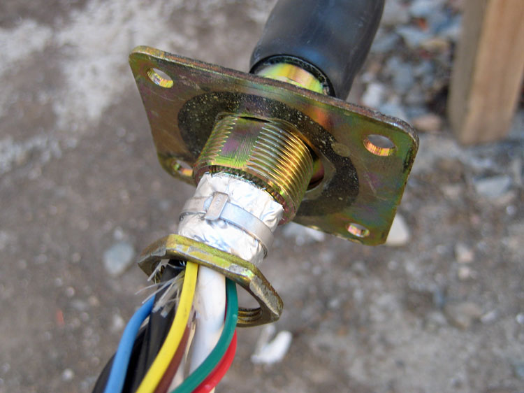
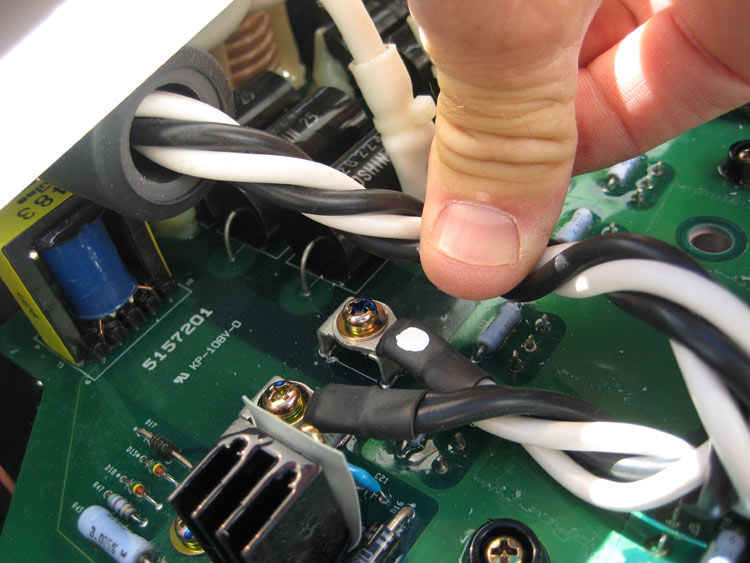
Here are all the new wires coming back into the charger, with the fixing nut in place. Passing those stiff power wires back through the choke is a bit of a challenge. Note the hard bend of the black and white wires after they ass through the hole at the base of the charger. Try taping the two wires together, but with the eye terminals staggered a bit. Might want to then attach a wire or string to help you pull through the choke.
Power wires routed through the choke, and bolted into place.
Click for |